Cisco ASA Active-Standby Configuration |
- Cisco ASA Active-Standby Configuration
- Sony finds no apparent Anonymous link to PlayStation attack
- Sony apologizes, details PlayStation Network attack
| Cisco ASA Active-Standby Configuration Posted: 01 May 2011 12:30 PM PDT On my previous post I talked about Cisco ASA Active/Active configuration. In this post I will describe Active/Standby redundancy which is used much more frequently compared with the active/active scenario. ASA Active/Standby failover/redundancy means connecting two identical ASA firewall units via LAN cable so that when one device or interface fails then the second one will take over the traffic and become the active device. During normal operation, the active ASA will be synchronizing its configuration to the standby unit. The configuration must be changed on active ASA. If we try to change the configuration on standby ASA, then the following warning will be displayed: ASA# configure terminal During active/standby failover, the active ASA receives all traffic flows and filters all network traffic while the secondary ASA is in the Ready mode. Therefore you should dimension each ASA device in such a way so that to be able to handle all traffic. ASA failover works in 2 modes: Stateful Failover and Regular Failover. During regular Failover, when Failover occurs, all active connections will be dropped. During Stateful Failover however, the active unit continually passes per-connection state to standby unit. When failover occurs, both ASA devices will have knowledge about all connections. The active ASA sends the state information of the following protocols/tables to the Standby ASA:
The following are not synchronized:
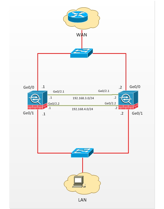
There are some predefined device requirements for allowing two ASAs to work in Failover mode: both of them must be the same model, both must have the same type and number of interfaces, the same volume of RAM and FLASH, the same licenses and the versions of ASA IOSs of both ASAs must match. If any of these requirements is not satisfied, then they cannot work in failover mode. Let's consider an example of active/standby Failover configuration (see diagram below). The Outside interfaces on ASAs are Ge0/0 and LAN interfaces are Ge0/1. For Failover we will use Ge0/2, particularly Ge0/2.1 will be the Failover interface and Ge0/2.2 the state interface (by which the information about protocol States will be exchanged). Note that you don't have to use two different connections for Failover and State. They can share the same connection/interface.
Configuration Active Unit Configuration: Note: Always start with the active ASA first. !Assign IP address to outside interface. During Failover the primary IP address will be assigned to Standby Unit. !Assign IP address to inside interface. During Failover the primary IP address will be assigned to Standby Unit. !enable LAN Failover. !set that unit as primary. !Define Failover Interface. In this documentation, the "failover" (interface name for GigabitEthernet0/2.1) is used as a failover interface. !Assign IP address to Failover Interfaces. In this documentation, the "state" (interface name for GigabitEthernet0/2.2) is used as a State !Define stateful Failover interface !Assign IP addresses to Stateful Failover interfaces !enable Failover Note: Issue the failover command on the primary device first, and then issue it on the secondary device. After you issue the failover command on the secondary device, the secondary device immediately pulls the configuration from the primary device and sets itself as standby. The primary ASA stays up and passes traffic normally and marks itself as the active device. From that point on, whenever a failure occurs on the active device, the standby device comes up as active. Standby Unit Configuration: ! enable LAN Failover !Define the failover interface !assign IP address to failover interface !set this unit as secondary ! Enable failover. After the above is completed, configuration replication will start with the following message: "Beginning configuration replication: Sending to mate" ………. All configuration commands will be done on Primary unit from now on. Connect to the primary unit and issue the command "write memory" to save the configuration. Run also the command "write standby" to save the config to the secondary device. Verification: !show failover on Primary ASA Stateful Failover Logical Update Statistics ! show failover on secondary unit. Stateful Failover Logical Update Statistics |
| Sony finds no apparent Anonymous link to PlayStation attack Posted: 01 May 2011 06:35 AM PDT |
| Sony apologizes, details PlayStation Network attack Posted: 01 May 2011 12:45 AM PDT |
| You are subscribed to email updates from "Cisco" via Ehsan in Google Reader To stop receiving these emails, you may unsubscribe now. | Email delivery powered by Google |
| Google Inc., 20 West Kinzie, Chicago IL USA 60610 | |


0 comments:
Post a Comment